单击打开
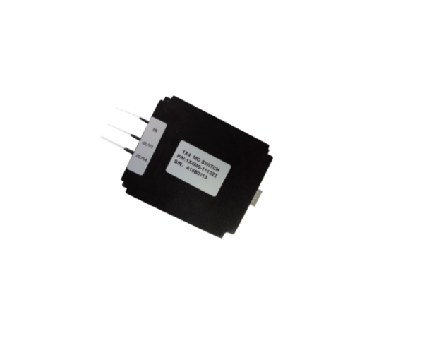
磁光开关保偏1×4M
Features
No moving parts,best durability
Ultra fast switching speed
Extremely stable latching mode
Easy to route -all fibers on sameside
Exceptional reliability and stability
Applications
Optical switching
High speed protection
System monitoring
Test & measurement
Fiber-opticssensingsystem
Dimensions Drawing (mm)

Ordering Information: HC-MO-1×4M-PM-A-B-C-D-E-F-G
|
A |
B |
C |
D |
E |
F |
G |
|
Working Mode |
Switching Speed |
Operating Wavelength |
Fiber Type |
Fiber Tuber |
Fiber Length |
Connector Type |
|
1.Regular 2.Bidirectional
|
1.200~400us
|
1.CBand 2. L Band 3. C & L Band 4. Others
|
1.PM98 2.PM15 3.PM13 4.Others |
1.250μm fiber 2. 900μm fiber 3. Others |
1.0.5 +/- 0.1 m 2. 1.0 +/- 0.1 m 3. Others |
0.No Connector 1. FC/UPC 2. FC/APC 3. SC/UPC 4. SC/APC 5. LC/PC 6. MU/PC 7. Others |
|
Item |
Unit |
Parameters |
Notes |
|
|
Unidirectional |
Bidirectional |
|||
|
Wavelength Range |
nm |
1525 ~ 1565 |
|
|
|
Insertion Loss |
dB |
1.8 (Typ.); 2.2 (Max.) |
2.0 (Typ.); 2.4 (Max.) |
|
|
Return Loss |
dB |
40 |
30 |
|
|
Crosstalk |
dB |
40 |
30 |
|
|
ER |
dB |
≥17 |
|
|
|
PMD |
ps |
0.2 |
|
|
|
Repeatability |
dB |
+/- 0.01 |
|
|
|
Durability |
cycles |
> 30 Billions |
|
|
|
Switching Speed |
μs |
200~400 |
|
|
|
Operating Temperature |
°C |
-5 ~ 70 |
|
|
|
Storage Temperature |
°C |
-40 ~ 85 |
|
|
|
Maximum Optical Power |
mW |
500 |
|
|
|
Dimension( L×W×H ) |
mm |
90×76×17.5 |
|
|
*.All the specifications are based on the devices without connector, and guaranteed over wavelength, polarization and temperature.
Electrical Specifications
|
Parameter |
Specification |
Unit |
|
Switching Speed |
200~400 |
μs |
|
Switching Voltage(VCC) |
5 (+/-5%) |
V |
|
Switching Current |
< 200 |
mA |
|
Pulse Width(typical) |
1000 |
μs |
|
Claim Frequency |
<800 |
Hz |
*. for electrical specifications related to other switching speed, please contact us.
Pin Definition Pin
|
Pin No. |
Pin1 |
Pin2 |
Pin3 |
Pin4 |
Pin5 |
Pin6 |
|
Definition |
VCC |
GND |
Ctrl 0 |
Ctrl 1 |
NA |
NA |
Pin Control Signal Corresponding to Switching Status:
Table1: Pin control signal corresponding to switching status for unidirectional switch
|
Ctrl 0 |
0 |
0 |
1 |
1 |
0 |
0 |
1 |
1 |
|
Ctrl 1 |
0 |
1 |
0 |
1 |
0 |
1 |
0 |
1 |
|
Optical Path |
IN→OUT 1 |
IN→OUT 2 |
IN→OUT 3 |
IN→OUT 4 |
OUT4→IN |
OUT3→IN |
OUT2→IN |
OUT1→IN |
Table2: Pin control signal corresponding to switching status for bidirectional switch
|
Ctrl 0 |
0 |
0 |
1 |
1 |
|
Ctrl 1 |
0 |
1 |
0 |
1 |
|
Optical Path |
IN←→OUT 1 |
IN←→OUT 2 |
IN←→OUT 3 |
IN←→OUT 4 |
