单击打开
视频专用模块
Descriptions
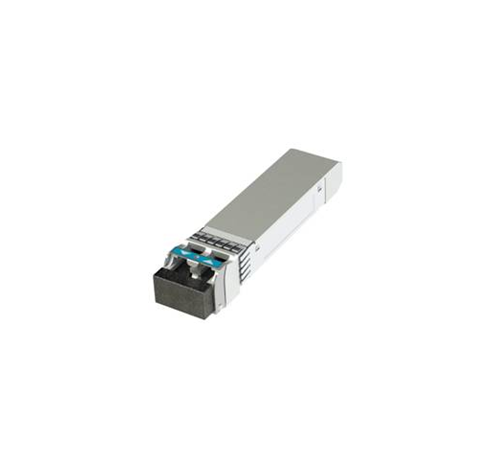
The Optical Extender Module is designed to transmit and receive data signal with its’ control signal. The module is capable of sending over 10.5Gbps of data through one single mode fiber. The module integrates proprietary optical sub- assembly (OSA) and circuitries of which includes four 3.5Gbps channels with reaching distance of over 1000 meters.
Features
Support Four High Speed TMDS Signals Transmission
Single LC Receptacle Optical Interface
Single-Mode and Multi-Mode Fiber Application
Forward Channels (TMDS 0 / 1 / 2) Maximum Data Rate : Up to 3.5 Gbps+3.3V Power Supply
Metal Based Enclosure for Better Heat Dissipation
Support Hot Pluggable : Easy to Installation , Upgrade and Replacement
Pin Definition and Descriptions


|
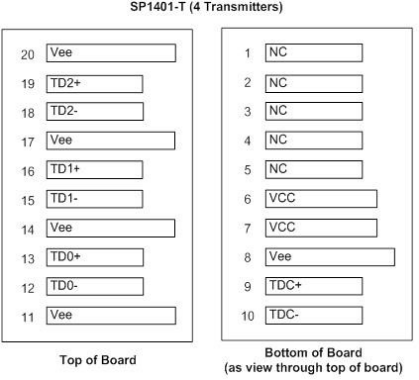
SP1401-T ( 4Transmitters ) |
|||
|
Pin No. |
Pin Name |
Description |
I/O / Level |
|
1 |
NC |
No Connect (Internal Use) |
-- |
|
2 |
NC |
No Connect (Internal Use) |
-- |
|
3 |
NC |
No Connect (Internal Use) |
-- |
|
4 |
NC |
No Connect (Internal Use) |
-- |
|
5 |
NC |
No Connect (Internal Use) |
-- |
|
6 |
VCC |
+3.3V Power Input |
Input |
|
7 |
VCC |
+3.3V Power Input |
Input |
|
8 |
Vee |
Signal Ground |
Input |
|
9 |
TDC+ |
TMDS Non-Inverted Clock Input |
Input /TMDS |
|
10 |
TDC- |
TMDS Inverted Inverted Clock Input |
Input /TMDS |
|
11 |
Vee |
Signal Ground |
Input |
|
12 |
TD0- |
TMDS Inverted Data0 Input |
Input /TMDS |
|
13 |
TD0+ |
TMDS Non-Inverted Data0 Input |
Input /TMDS |
|
14 |
Vee |
Signal Ground |
Input |
|
15 |
TD1- |
TMDS Inverted Data1 Input |
Input /TMDS |
|
16 |
TD1+ |
TMDS Non-Inverted Data1 Input |
Input /TMDS |
|
17 |
Vee |
Signal Ground |
Input |
|
18 |
TD2- |
TMDS Inverted Data2 Input |
Input /TMDS |
|
19 |
TD2+ |
TMDS Non-Inverted Data2 Input |
Input /TMDS |
|
20 |
Vee |
Signal Ground |
Input |
|
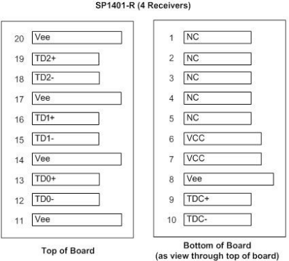
SP1401-R ( 4 Receivers ) |
|||
|
Pin No. |
Pin Name |
Description |
I/O / Level |
|
1 |
NC |
No Connect (Internal Use) |
-- |
|
2 |
NC |
No Connect (Internal Use) |
-- |
|
3 |
NC |
No Connect (Internal Use) |
-- |
|
4 |
NC |
No Connect (Internal Use) |
-- |
|
5 |
NC |
No Connect (Internal Use) |
-- |
|
6 |
VCC |
+3.3V Power Input |
Input |
|
7 |
VCC |
+3.3V Power Input |
Input |
|
8 |
Vee |
Signal Ground |
Input |
|
9 |
TDC+ |
TMDS Non-Inverted Clock Output |
Output /TMDS |
|
10 |
TDC- |
TMDS Inverted Inverted Clock Output |
Output / TMDS |
|
11 |
Vee |
Signal Ground |
Input |
|
12 |
TD0- |
TMDS Inverted Data0 Output |
Output / TMDS |
|
13 |
TD0+ |
TMDS Non-Inverted Data0 Output |
Output / TMDS |
|
14 |
Vee |
Signal Ground |
Input |
|
15 |
TD1- |
TMDS Inverted Data1 Output |
Output / TMDS |
|
16 |
TD1+ |
TMDS Non-Inverted Data1 output |
Output / TMDS |
|
17 |
Vee |
Signal Ground |
Input |
|
18 |
TD2- |
TMDS Inverted Data2 Output |
Output / TMDS |
|
19 |
TD2+ |
TMDS Non-Inverted Data2 Output |
Output / TMDS |
|
20 |
Vee |
Signal Ground |
Input |
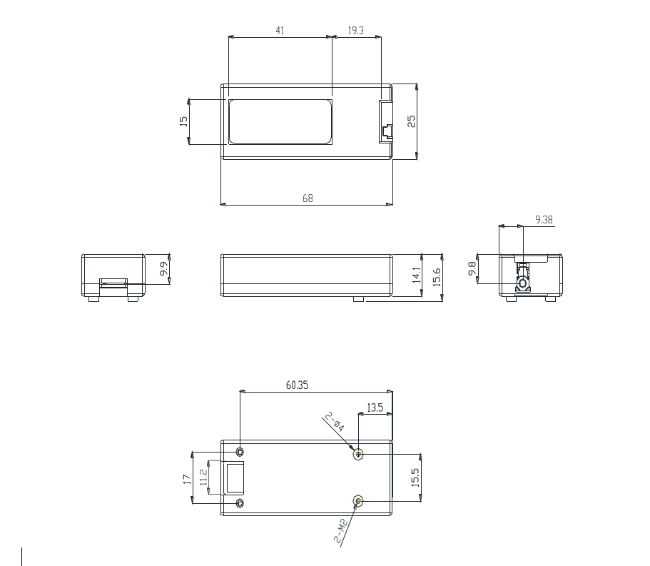
Mechanical Outlines
( Units in mm )
( Dimension : W= 25mm / L=68mm / H= 14mm )

General Characteristics
|
Parameter |
Symbol |
Min |
Typ |
Max |
Unit |
|
Operating Temperature |
Tc |
+0 |
-- |
+55 |
℃ |
|
Storage Temperature |
TS |
-20 |
-- |
85 |
℃ |
Electrical Characteristics
( VCC=+3.3V;Tc= +0oC~+55oC unless specified)
|
Parameter |
Symbol |
Min |
Typ |
Max |
Units |
|
Supply Voltage |
Vcc |
+3.15V |
+3.3V |
+3.45 |
V |
|
Supply Current |
Icc |
-- |
-- |
TBD |
A |
|
TMDS Signal Line Speed(TD2 / TD1 / TD0 /TC Channels) |
DH |
-- |
3.5 |
-- |
Gbps |
|
TMDS Differential Data Input Swing |
Vin-pp |
600 |
-- |
1200 |
mV |
|
TMDS Differential Data Output Swing |
Vout-pp |
600 |
-- |
1200 |
mV |
