
单击打开
1.25G CWDM 40km 光模块
HC’HXSC-1Lx41xF Small Form Factor Pluggable (SFP) transceivers are compatible with the Small Form Factor Pluggable Multi-Sourcing Agreement (MSA), The transceiver consists of five sections: the LD driver, the limiting amplifier, the digital diagnostic monitor, the CWDM DFB laser and the PIN photo-detector .The module data link up to 40km in 9/125um single mode fiber.
The optical output can be disabled by a TTL logic high-level input of Tx Disable, and the system also can disable the module via I2C. Tx Fault is provided to indicate that degradation of the laser. Loss of signal (LOS) output is provided to indicate the loss of an input optical signal of receiver or the link status with partner. The system can also get the LOS (or Link)/Disable/Fault information via I2C register access.
Features
Up to 1250Mb/s data links
CWDM DFB laser transmitter and PIN photo-detector
Up to 40km on 9/125µm SMF
Hot-pluggable SFP footprint
Duplex LC/UPC type pluggable optical interface
Low power dissipation
Metal enclosure, for lower EMI
RoHS compliant and lead-free
Support Digital Diagnostic Monitoring interface
Single +3.3V power supply
Compliant with SFF-8472
Case operating temperature Commercial: 0 ~ +70℃ Extended: -10 ~ +80℃
Industrial: -40 ~ +85℃
Digital Diagnostic Functions
|
Parameter |
Symbol |
Min. |
Max |
Unit |
Notes |
|
Temperature monitor absolute error |
DMI_ Temp |
-3 |
3 |
degC |
Over operating temp |
|
Supply voltage monitor absolute error |
DMI _VCC |
-0.15 |
0.15 |
V |
Full operating range |
|
RX power monitor absolute error |
DMI_RX |
-3 |
3 |
dB |
|
|
Bias current monitor |
DMI_ bias |
-10% |
10% |
mA |
|
|
TX power monitor absolute error |
DMI_TX |
-3 |
3 |
dB |
|
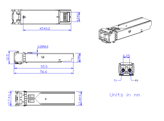
Mechanical Dimensions
Figure2. Mechanical Outline
Absolute Maximum Ratings
|
Parameter |
Symbol |
Min |
Max |
Unit |
Notes |
|
Storage Temperature |
TS |
-40 |
85 |
oC |
|
|
Operating Case Temperature |
Tcase |
See order Information |
oC |
|
|
|
Power Supply Voltage |
VCC |
-0.3 |
3.6 |
V |
|
|
Relative Humidity (non-condensation) |
RH |
5 |
95 |
% |
|
|
Damage Threshold |
THd |
5 |
|
dBm |
|
Recommended Operating Conditions and Power Supply Requirements
|
Parameter |
Symbol |
Min |
Typical |
Max |
Unit |
Notes |
|
Operating Case Temperature |
TOP |
0 |
|
70 |
oC |
commercial |
|
-10 |
|
80 |
extended |
|||
|
-40 |
|
85 |
industrial |
|||
|
Power Supply Voltage |
VCC |
3.135 |
3.3 |
3.465 |
V |
|
|
Data Rate |
|
|
1250 |
|
Mb/s |
|
|
Control Input Voltage High |
|
2 |
|
Vcc |
V |
|
|
Control Input Voltage Low |
|
0 |
|
0.8 |
V |
|
|
Link Distance (SMF) |
D |
|
|
40 |
km |
9/125um |
Specification of Transmitter Electrical Characteristics
|
Parameter |
Symbol |
Min. |
Typical |
Max |
Unit |
Notes |
|
|
Power Consumption |
P |
|
|
1.0 |
W |
commercial |
|
|
|
|
1.5 |
Industrial |
||||
|
Supply Current |
Icc |
|
|
280 |
mA |
commercial |
|
|
|
|
450 |
Industrial |
||||
|
Transmitter |
|||||||
|
Single-ended Input Voltage Tolerance |
VCC |
-0.3 |
|
4.0 |
V |
|
|
|
Differential Input Voltage Swing |
Vin,pp |
200 |
|
2400 |
mVpp |
|
|
|
Differential Input Impedance |
Zin |
90 |
100 |
110 |
Ohm |
|
|
|
Transmit Disable Assert Time |
|
|
|
5 |
us |
|
|
|
Transmit Disable Voltage |
Vdis |
Vcc-1.3 |
|
Vcc |
V |
|
|
|
Transmit Enable Voltage |
Ven |
Vee-0.3 |
|
0.8 |
V |
|
|
|
Receiver |
|||||||
|
Differential Output Voltage Swing |
Vout,pp |
500 |
|
900 |
mVpp |
|
|
|
Differential Output Impedance |
Zout |
90 |
100 |
110 |
Ohm |
|
|
|
Data output rise/fall time |
Tr/Tf |
|
100 |
|
ps |
20% to 80% |
|
|
LOS Assert Voltage |
VlosH |
Vcc-1.3 |
|
Vcc |
V |
|
|
|
LOS De-assert Voltage |
VlosL |
Vee-0.3 |
|
0.8 |
V |
|
|
Optical Characteristics
|
Parameter |
Symbol |
Min. |
Typical |
Max |
Unit |
Notes |
|
Transmitter |
||||||
|
Center Wavelength |
λC |
X-6.5 |
X |
X+6.5 |
nm |
1 |
|
Spectrum Bandwidth(RMS) |
σ |
|
|
1 |
nm |
|
|
Side Mode Suppression Ratio |
SMSR |
30 |
|
|
dB |
|
|
Average Optical Power |
PAVG |
-5 |
|
0 |
dBm |
|
|
Optical Extinction Ratio |
ER |
9 |
|
|
dB |
|
|
Transmitter OFF Output Power |
POff |
|
|
-45 |
dBm |
|
|
Transmitter Eye Mask |
|
Compliant with 802.3z(class 1 laser safety) |
2 |
|||
|
Receiver |
||||||
|
Center Wavelength |
λC |
1270 |
|
1610 |
nm |
|
|
Receiver Sensitivity (Average Power) |
Sen. |
|
|
-24 |
dBm |
3 |
|
Input Saturation Power (overload) |
Psat |
-1 |
|
|
dBm |
|
|
LOS Assert |
LOSA |
-36 |
|
|
dB |
4 |
|
LOS De-assert |
LOSD |
|
|
-25 |
dBm |
4 |
|
LOS Hysteresis |
LOSH |
0.5 |
2 |
6 |
dBm |
|
Notes:
1. X: See HXSC-1Lx41x Wavelength List. The industrial grade module contains a TEC circuit.
2. Transmitter eye mask definition.
3. Measured with Light source 1270~1610nm, ER=9dB; BER =<10^- 12 @PRBS=2^7-1 NRZ
4. When LOS de-asserted, the RX data+/- output is High-level (fixed).
Digital Diagnostic Functions
|
Parameter |
Symbol |
Min. |
Max |
Unit |
Notes |
|
Temperature monitor absolute error |
DMI_ Temp |
-3 |
3 |
degC |
Over operating temp |
|
Supply voltage monitor absolute error |
DMI _VCC |
-0.15 |
0.15 |
V |
Full operating range |
|
RX power monitor absolute error |
DMI_RX |
-3 |
3 |
dB |
|
|
Bias current monitor |
DMI_ bias |
-10% |
10% |
mA |
|
|
TX power monitor absolute error |
DMI_TX |
-3 |
3 |
dB |
|
