Features
Modular Design
Non-Blocking Switching
“any-to-any” switch
High Reliability and stability
Application
OADM
OXC
Data Center
Instrumentation
Compliance
Telcordia GR-1221
Telcordia GR-1073
Optical Route

Specifications
Single Mode
Parameters | Unit | MEMS M×N-SM | |
Working Wavelength | nm | 1260-1650 | |
Testing Wavelength | nm | 1310/1550/1625/1650 | |
Insertion Loss | dB | @CWL Single-band ≤1.6 (M≤8, N≤8) ≤2.0 (M≤16, N≤16) ≤2.6 (M≤32, N≤32) ≤3.0 (M≤64, N≤64) | @CWL Dual-band ≤2.0 (M≤8, N≤8) ≤2.4 (M≤16, N≤16) ≤3.0 (M≤32, N≤32) ≤3.4 (M≤64, N≤64) |
WDL | dB | ≤0.6 | |
PDL | dB | ≤0.3 | |
Return Loss | dB | ≥45 | |
Crosstalk | dB | ≥50 | |
Repeatability | dB | ≤±0.1 | |
Switching Time | ms | ≤10 | |
Durability | times | ≥109 | |
Input Optical Power | mW | ≤500 | |
Operating Voltage | V | DC 5V±10% | |
Operating Current | A | ≤0.5 (M+N≤16) ≤0.8 (M+N≤32) ≤2.0 (M+N≤64) ≤4.0 (M+N≤128) | |
Operating Temp. | °C | -5 ~ +75 | |
Storage Temp. | °C | -40 ~ +85 | |
Dimension | mm | M5: 110×141×12mm (M+N≤16) M6: 320×200×18mm (M+N≤48) M7: 320×240×30mm (M+N≤64) customization:64<M+N≤128 | |
1.Within operating temperature and all SOP. 2.Excluding connector. 3.WDL is measured in a ±20nm range at 23°C. | |||
Multi-Mode
Parameters | Unit | MEMS M×N-MM | |
Working Wavelength | nm | 850±30, 1310±30 | |
Testing Wavelength | nm | 850/1310 | |
Insertion Loss | dB | @CWL Single-band ≤1.6 (M≤12, N≤12) ≤2.0 (M≤16, N≤16) | @CWL Dual-band ≤2.0 (M≤12, N≤12) ≤2.4 (M≤16, N≤16) |
WDL | dB | ≤0.6 | |
PDL | dB | ≤0.4 | |
Return Loss | dB | ≥30 | |
Crosstalk | dB | ≥30 | |
Repeatability | dB | ≤±0.1 | |
Switching Time | ms | ≤15 | |
Durability | times | ≥109 | |
Input Optical Power | mW | ≤500 | |
Operating Voltage | V | DC 5V±10% | |
Operating Current | A | ≤0.5 (M+N≤16) ≤0.8 (M+N≤32) | |
Operating Temp. | °C | -5 ~ +70 | |
Storage Temp. | °C | -40 ~ +85 | |
Dimension | mm | M5: 110×141×12mm (M+N≤16) M6: 320×200×18mm (M+N≤32) customization:32<M+N≤128 | |
1.Within operating temperature and all SOP. 2.Excluding connector. 3.WDL is measured in a ±20nm range at 23°C. | |||
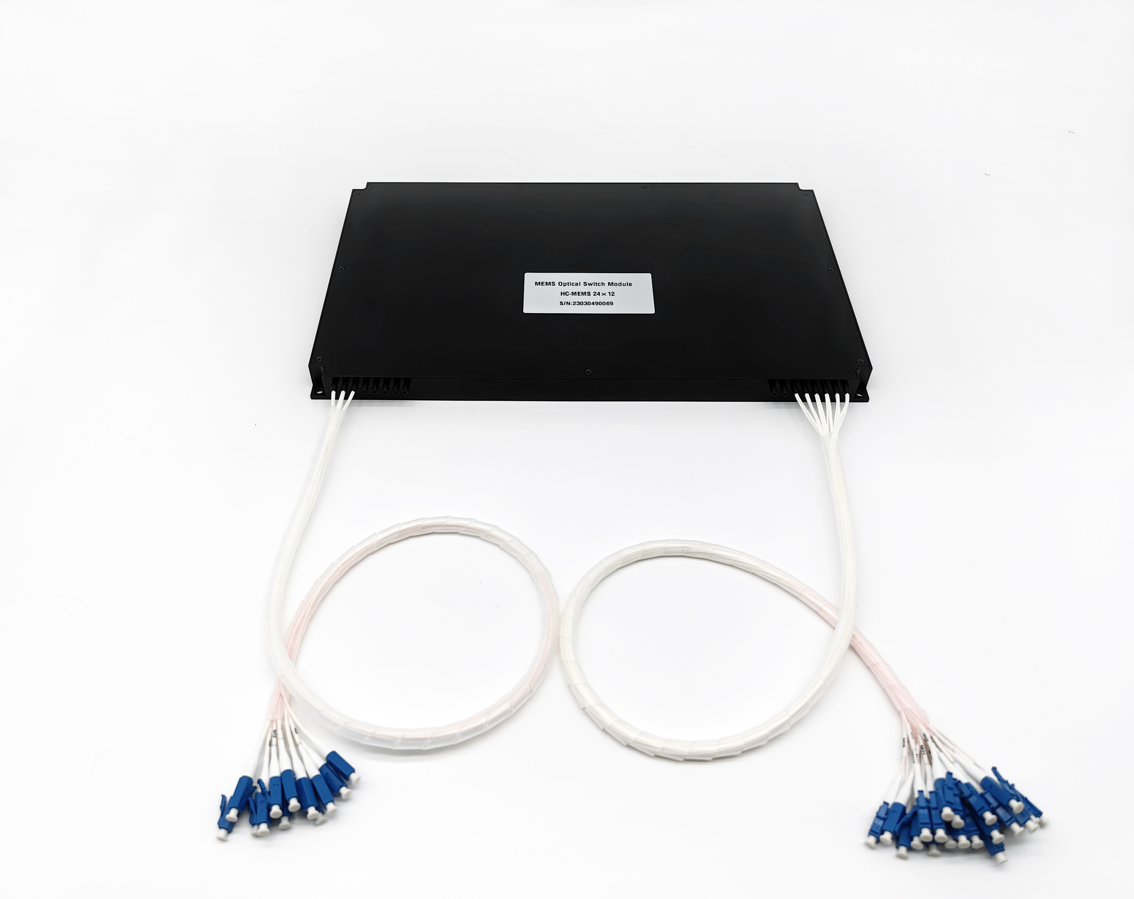
Dimension
M5:110×141×12mm
![NJ{OOIQ6D2Z4368ZJAX@N]B.png](/uploads/20231215/202312150954477810.png "NJ{OOIQ6D2Z4368ZJAX@N]B.png")
M6:320×200×18mm
2MUYHDH}[WM_XB.png")
M7:320×240×30mm

Pin Configurations
Pin# | Signal name | Type | Description |
1 | NC | ||
2 | NC | ||
3 | VCC | Power | Power supply,DC 5V,1.0A |
4 | NC | ||
5 | NC | ||
6 | GND | Power | GND |
7 | NC | ||
8 | NC | ||
9 | TXD | Output | RS232 TX(3.3V TTL) |
10 | RXD | Input | RS232 RX(3.3V TTL) |
11 | NC | ||
12 | NC | ||
13 | NC | ||
14 | NC | ||
15 | NC | ||
16 | NC |
Note: The electrical interfaces of M5, M6 and M7 modules should use MOLEX's 87833-1620, and the customer connectors should use MOLEX's 87568-1694.
Ordering Information: MEMS M×N-A-B-C-D-E-F-G
A | B | C | D | E | F | G |
Mode | Wavelength | Dimension | Fiber Type | Fiber Dimension | Fiber Length | Connector |
SM: Single Mode | 85:850nm | 1:110×141×12mm | 5:50/125 | 025:Φ0.25mm | 05:0.5m | 00: None |
MM: Multi-Mode | 13:1310nm | 2:200×180×18mm | 6:62.5/125 | 09:Φ0.9mm | 10:1.0m | FP: FC/UPC |
14:1490nm | X:other | 9:9/125 | X:other | 15:1.5m | FA: FC/APC | |
15:1550nm | X:other | X:other | SP: SC/UPC | |||
162:1625nm | SA: SC/APC | |||||
165:1650nm | LP: LC/UPC | |||||
13/15: 1310/1550nm | MP:MPO | |||||
X:other | X:other |
 CN
CN EN
EN