产品名称:光纤线路保护设备
System Description
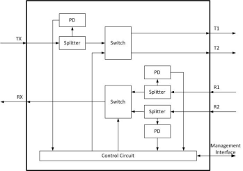
OLP (Optical Fiber Line Auto Switch Protection System) is a product that used in the protection of optical transmission line, it can realize optical power real-time monitoring and automatic optical fiber line switching.
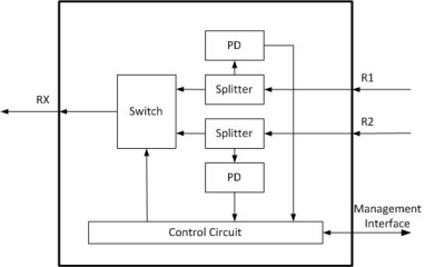
In optical transmission network, the OLP monitor the optical power of the Primary and Secondary fiber in real time. When the Primary is accidentally broken or the performance is degraded, the OLP will automatically switch the working channel from Primary to Secondary to realize the protection of optical fiber line.
![VH{MU$[@NJWE~T]6AT_{P}C.png VH{MU$[@NJWE~T]6AT_{P}C.png](/uploads/20230214/202302141448017822.png)
Advantages
l Working in the optical layer, transparent transmission to optical signals.
l High optical performance.
l Carrier grade switching speed.
l Support dual power supplies for redundancy.
l Support NMS for unified OAM.
Applications
l Optical fiber line auto switch protection.
l Real-time monitoring of fiber quality by optical power.
l Emergency dispatching of working routes.
Equipment Types
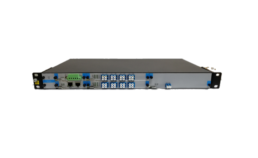
Compact OLP (1U compact type)

Pluggable OLP (1/2/4U pluggable type)

Diagram
![5HVEZK[%]6NQ%Z{GZ%L]S6B.png 5HVEZK[%]6NQ%Z{GZ%L]S6B.png](/uploads/20230214/202302141452277986.png)
1+1

1:1

1-1
Compact OLP
Features
l Low cost OLP solution.
l 1U compact size for easy deployment.
l Support panel key control with LCD display.
l Support 1+1, 1:1, 1-1 three kinds of protection methods.
Outline
Front

Back

1: LCD Display
2: LAN and RS-232 interface: management interface
· LAN: RJ-45 connector
· RS-232: DB9 male connector
3: Indicated LED
LED | Indication | Descriptions |
Power1 Power2 | Power Supply status | On: Power on Off: Power off |
Run | Equipment running status | Flashes 1 time/second |
Auto | Working mode status | On: Auto mode Off: Manual mode |
Pri, Sec | Working channel status | Pri on: Working on Primary Channel Sec on: Working on Secondary Channel |
R1 | RX level status of Primary channel | Green: normal (the RX level is higher than the switching threshold) Red: Alarm (the RX level is lower than the switching threshold) |
R2 | RX level status of Secondary channel | Green: normal (the RX level is higher than the switching threshold) Red: Alarm (the RX level is lower than the switching threshold) |
TX | Connection status between OLP and transmission equipment | Green: Normal (OLP received optical signal from transmission equipment) Red: Alarm (OLP do not received optical signal from transmission equipment) |
Ls | Working status of internal Light Source | Green: Normal Off: Internal LS is inactive or unassembled Flash with Green light: RX level is lower than the switching threshold. (Internal LS is available for 1:1 only, which is used for monitoring standby channel) |
4: Panel key
Enter: Long press to enter or exit the menu. Short press to confirm and save the setting.
▲▼:Select the menu.
Exit: Exit the menu.
5: Optical interface
Port | Connection |
TX | Connect to TX port of transmission equipment |
RX | Connect to RX port of transmission equipment |
T1 | Connect to TX port of primary optical fiber |
R1 | Connect to RX port of primary optical fiber |
T2 | Connect to TX port of secondary optical fiber |
R2 | Connect to RX port of secondary optical fiber |
6: -48V DC connector
7: 220V AC connector
Specifications
Parameters | Unit | 1:1 | 1+1 | 1-1 |
Working Wavelength | nm | 1310±50nm, 1550±50nm | ||
Optical Power Monitoring Range | dBm | +23 ~ -50 | ||
Optical Power Monitoring Accuracy | dB | ±0.25 | ||
Optical Power Monitoring Resolution | dB | ±0.01 | ||
Return Loss | dB | ≥55 | ||
PDL | dB | ≤0.05 | ||
WDL | dB | ≤0.1 | ||
Insertion Loss | dB | TX<1.2 RX<1.2 | TX<4 RX<1.2 | <1.2 |
Switching Time | ms | <35 | <15 | <15 |
Working Life | times | >107 | ||
Working Temperature | °C | -10 ~ +60 | ||
Storage Temperature | °C | -20 ~ +75°C | ||
Power Supply | V | -48V DC, 220V AC, Support dual PS | ||
Power down Status | Maintain or Switch to backup path | |||
Optical Interface | SC/LC (selectable) | |||
Management Interface | RJ-45, RS-232 | |||
Rack Size | 19’inch, 1U height | |||
Pluggable OLP
Features
l Highly-scalable platform by pluggable design.
l High integration, large capacity. (2ch OLP per 0.5U card)
l 3 types chassis: 1U with 4 slots, 2U with 8slots, 4U with 16 slots.
l Optional OTDR test function for fiber OAM.
l Optional EDFA to achieve long-haul transmission.
Outline
1U

2U

Specifications
General
1) Environmental Condition
l Working Temperature: -5°C to +55°C
l Humidity: ≤ 85% (@ 25°C)
2) Power Supply
l Power Supply: -48V/DC±20% (85-264)V/AC
l Power consumption: less than 50W in full configuration.
3) Chassis dimension
Chassis | Dimension (W×D×H) |
1U | 483×240×44mm |
2U | 483×240×89mm |
4U | 483×240×176mm |
Power Unit (PWU)
Outline:


AC Card (1U height) DC Card (0.5U height)
Specifications:
AC Input : 85-264V/AC
DC Input : -48V/DC ± 20%
Network Management Unit (NMU)
Outline:

Specifications:
Ethernet Port : 10/100Mbps (RJ-45)
Console : for debugging only.
Optical Line Protection Card (OLP)
Outline:

Specifications:
Parameters | Unit | 1:1 | 1+1 | 1-1 |
Working Wavelength | nm | 1310±50nm, 1550±50nm | ||
Optical Power Monitoring Range | dBm | +23 ~ -50 | ||
Optical Power Monitoring Accuracy | dB | ±0.25 | ||
Optical Power Monitoring Resolution | dB | ±0.01 | ||
Switching Time | ms | <35 | <15 | <15 |
Insertion Loss | dB | TX<1.2 RX<1.2 | TX<4 RX<1.2 | <1.2 |
Return Loss | dB | ≥55 | ||
Power down Status | Maintain or Switch to backup path | |||
Optical Interface | LC/UPC | |||
Channels | Max.2 per card | |||
Working Parameters
Working Mode
Auto mode: The channels are switch automatically according to the switching threshold.
Manual mode: The channels are switch by setting manually.
OLP support Manual mode auto-return to Auto mode. In a certain period of time, if the OLP does not have any manual operation, Manual mode will automatically return to Auto mode. The factory default setting is 30 minutes. The available value is 1 to 999 minutes. Auto-return function is disabled if the value is set to 0.
Notes: The OLP equipment should be working on Auto mode after operation completed for preventing protection failure.
Working Channel
OLP will select the working channel automatically according to the optical line status while working under Auto mode.
Working channel can be selected manually by panel key, commands or NMS . While switching the working channel, the Working Mode will be changed to Manual automatically.
Working Wavelength
1310nm or 1550nm can be selected as working wavelength.
Switching Threshold
The factory default setting of switching threshold is -30dBm.
In case the optical power of Primary channel is lower than the threshold, OLP will switch the working channel to Secondary.
Switching Delay
Delay switching and Non-delay switching can be seleted in Auto working mode.
Delay switching: In case the optical power of Primary channel is lower than the threshold, OLP will switch the working channel to Secondary channel after M(M=1~999) seconds delay.
Non-Delay switching: In case the optical power of Primary channel is lower than the threshold, OLP will switch the working channel to Secondary channel immediately.
Working Channel Auto-Switching back
Auto Switching Back or Non-auto Switching Back can be selected.
In Auto switching back, while the primary optical line recover, OLP will switch the working channel from Secondary back to Primary automatically. In this mode, delay can be set from 1 to 999 minutes.
But in Non-auto switching back, the working channel will be maintain in the Secondary channel, even if the Primary channel has recovered.
Engineering Connection Diagram

Network Management System
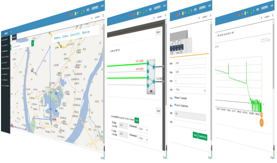
The OLP network management system can realize unified management and control of all OLP equipment.
Features:
l Support Windows OS.
l Web-based access, friendly operation.
l GIS platform for visualized management and location.
Functions:
l System Management.
l Equipment Management.
l GIS Topology Management
l OLP Management
l OTDR Test Management
l Alarm Management
l Report Management
