
单击打开
3.125G CWDM 光模块 SM
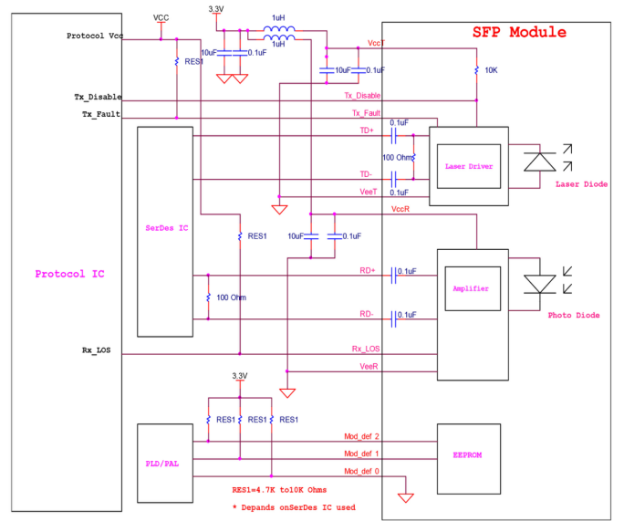
The optical output can be disabled by a TTL logic high-level input of Tx Disable, and the system also can disable the module via I2C. Tx Fault is provided to indicate that degradation of the laser. Loss of signal (LOS) output is provided to indicate the loss of an input optical signal of receiver or the link status with partner. The system can also get the LOS (or Link)/Disable/Fault information via I2C register access.
HC’s SF-CXX30-40D(A) Small Form Factor Pluggable (SFP) transceivers are compatible with the Small Form Factor Pluggable Multi-Sourcing Agreement (MSA). The transceiver consists of five sections: the LD driver, the limiting amplifier, the digital diagnostic monitor, the DFB laser and the PIN. The module data link up to 40KM in 9/125um single mode fiber.
KEY Features
Up to 3.125Gb/s data links
DFB laser transmitter and PIN receiver
Up to 40km on 9/125µm SMF
Hot-pluggable SFP footprint
Duplex LC/UPC type pluggable optical interface
Low power dissipation
Metal enclosure, for lower EMI
RoHS compliant and lead-free
Single +3.3V power supply
Support Digital Diagnostic Monitoring interface
Compliant with SFF-8472
Case operating temperature
Commercial: 0°C to +70°C
Industrial: -40°C to +85°C
Application
Switch to Switch Interface
Gigabit Ethernet
Switched Backplane Applications
Router/Server Interface
Other Optical Links
Recommend Circuit Schematic
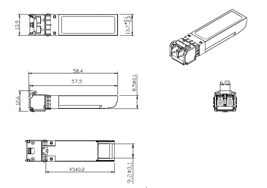
Mechanical Specifications (Unit: mm)
SF-CXX30-40D(A)
Regulatory Compliance
|
Feature |
Reference |
Performance |
|
Electrostatic discharge(ESD) |
IEC/EN 61000-4-2 |
Compatible with standards |
|
Electromagnetic Interference (EMI) |
FCC Part 15 Class B EN 55022 Class B (CISPR 22A) |
Compatible with standards |
|
Laser Eye Safety |
FDA 21CFR 1040.10, 1040.11 IEC/EN 60825-1,2 |
Class 1 laser product |
|
Component Recognition |
IEC/EN 60950 ,UL |
Compatible with standards |
|
ROHS |
2002/95/EC |
Compatible with standards |
|
EMC |
EN61000-3 |
Compatible with standards |
Absolute Maximum Ratings
|
Parameter |
Symbol |
Min. |
Typ. |
Max. |
Unit |
Note |
|
Storage Temperature |
Ts |
-40 |
|
85 |
ºC |
|
|
Relative Humidity |
RH |
5 |
|
95 |
% |
|
|
Power Supply Voltage |
VCC |
-0.5 |
|
4 |
V |
|
|
Signal Input Voltage |
|
-0.3 |
|
Vcc+0.3 |
V |
|
|
Receiver Damage Threshold |
|
5 |
|
|
dBm |
|
Recommended Operating Conditions
|
Parameter |
Symbol |
Min. |
Typ. |
Max. |
Unit |
Note |
|
Case Operating Temperature |
Tcase |
0 |
|
70 |
ºC |
Commercial |
|
-40 |
|
85 |
ºC |
Industrial |
||
|
Power Supply Voltage |
VCC |
3.13 |
3.3 |
3.47 |
V |
|
|
Power Supply Current |
ICC |
|
|
300 |
mA |
|
|
Power Supply Noise Rejection |
|
|
|
100 |
mVp-p |
100Hz to 1MHz |
|
Data Rate |
|
|
3125/3125 |
|
Mbps |
TX Rate/RX Rate |
|
Transmission Distance |
|
|
|
40 |
KM |
|
|
Coupled Fiber |
Single mode fiber |
9/125um SMF |
||||
Specification of Transmitter
|
Parameter |
Symbol |
Min. |
Typ. |
Max. |
Unit |
Note |
|
Average Output Power |
POUT |
-2 |
|
3 |
dBm |
Note (1) |
|
Extinction Ratio |
ER |
8.2 |
|
|
dB |
|
|
Center Wavelength |
λC |
(1XX0)-10 |
1XX0 |
(1XX0)+10 |
nm |
DFBLaser Note (2) Not(2) |
|
Side Mode Suppression Ratio |
SMSR |
30 |
|
|
dB |
|
|
Spectrum Bandwidth(-20dB) |
σ |
|
|
1 |
nm |
|
|
Transmitter OFF Output Power |
POff |
|
|
-45 |
dBm |
|
|
Differential Line Input Impedance |
RIN |
90 |
100 |
110 |
Ohm |
|
|
Output Eye Mask |
Compliant with G.957 (class 1 laser safety) |
|
Note (3) |
|||
Note:
(1): Measure at 2^23-1 NRZ PRBS pattern
(2):“XX” is: 27,29,31,33,35,37,39,41,43,45,47,49,51,53,55,57,59 and 61
(3): Transmitter eye mask definition
Electrical Interface Characteristics
|
Parameter |
Symbol |
Min. |
Typ. |
Max. |
Unit |
Note |
|
Transmitter |
||||||
|
Total Supply Current |
ICC |
|
|
A |
mA |
Note (1) |
|
Transmitter Disable Input-High |
VDISH |
2 |
|
Vcc+0.3 |
V |
|
|
Transmitter Disable Input-Low |
VDISL |
0 |
|
0.8 |
V |
|
|
Transmitter Fault Input-High |
VTxFH |
2 |
|
Vcc+0.3 |
V |
|
|
Transmitter Fault Input-Low |
VTxFL |
0 |
|
0.8 |
V |
|
|
Receiver |
||||||
|
Total Supply Current |
ICC |
|
|
B |
mA |
Note (1) |
|
LOSS Output Voltage-High |
VLOSH |
2 |
|
Vcc+0.3 |
V |
LVTTL |
|
LOSS Output Voltage-Low |
VLOSL |
0 |
|
0.8 |
V |
|
Note(1): A (TX) + B (RX) = 300mA (Not include termination circuit)
